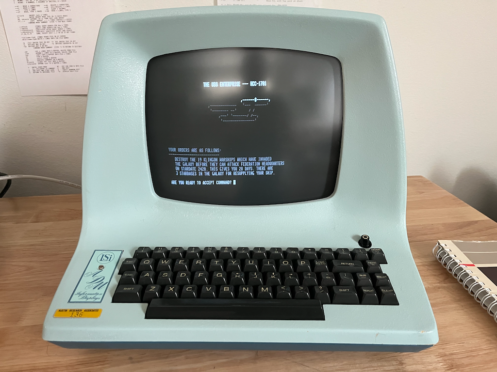
ADM-3A
The ADM-A3 was an early “affordable” video terminal from the mid-1970s, a time when teletypes were still in common use. It was famously the terminal Bill Joy used to write vi, which explains a few things.
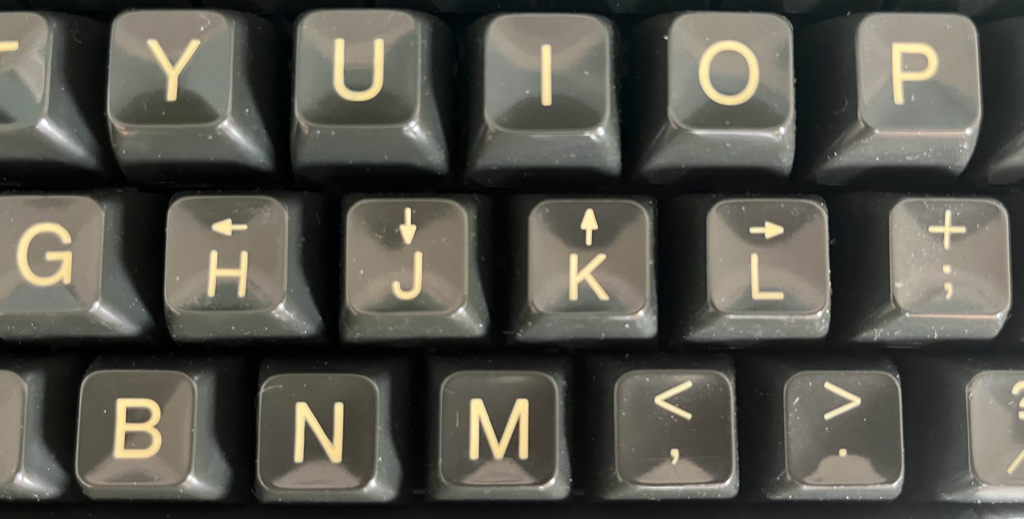
Mine showed up one day a few years ago, with a message from my friend Glen to go look on the front porch. The shape and color are from an age before beige boxes. It’s really striking, but the CRT cataracts are immediately visible and will require some attention.
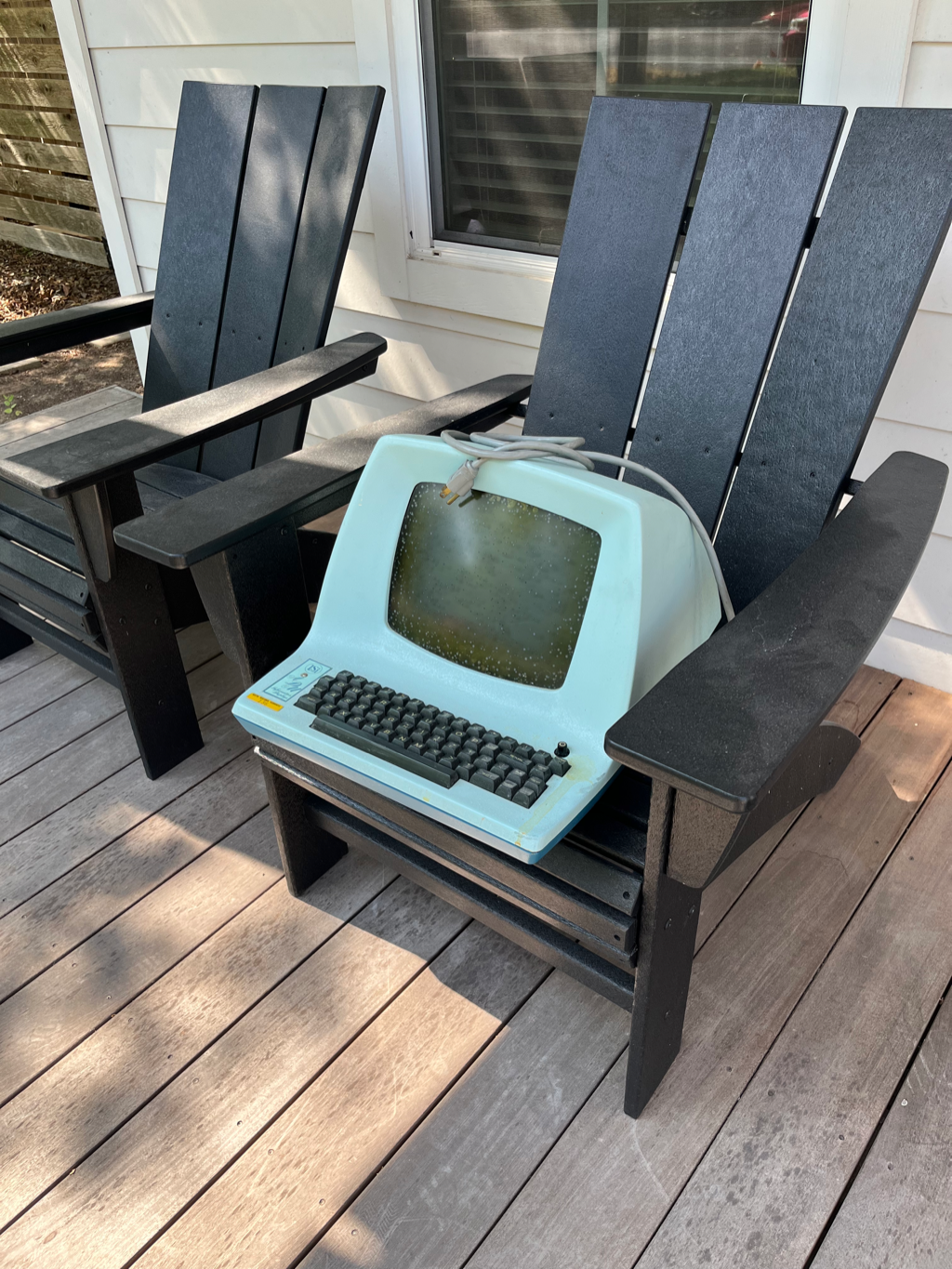
Initial Assessment
The terminal was dirty but mechanically in good shape and the little LSI nameplate was intact, which is rare. It opens like a clamshell, revealing a gorgeous PCB with a whole lot of 74-series logic ICs. Unlike later terminals, this one has no microprocessor inside. It’s all discrete.
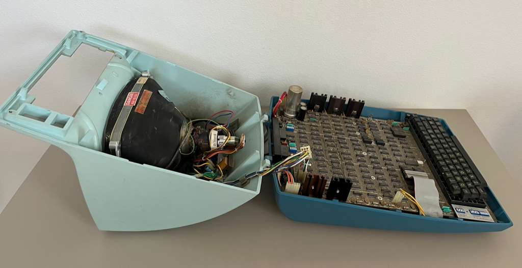
I was puzzled by the ribbon cable wrapping around to the back of the PCB and was very surprised to find that there was another PCB underneath, as well as the UART that had been in the socket where the ribbon cable was plugged in. The surprise card is an extremely rare RG512 graphics card that hooks into the serial stream, intercepts Tektronix vector graphics commands, and draws them using its own video circuitry that’s mixed into the main signal going to the CRT. An amazing find.
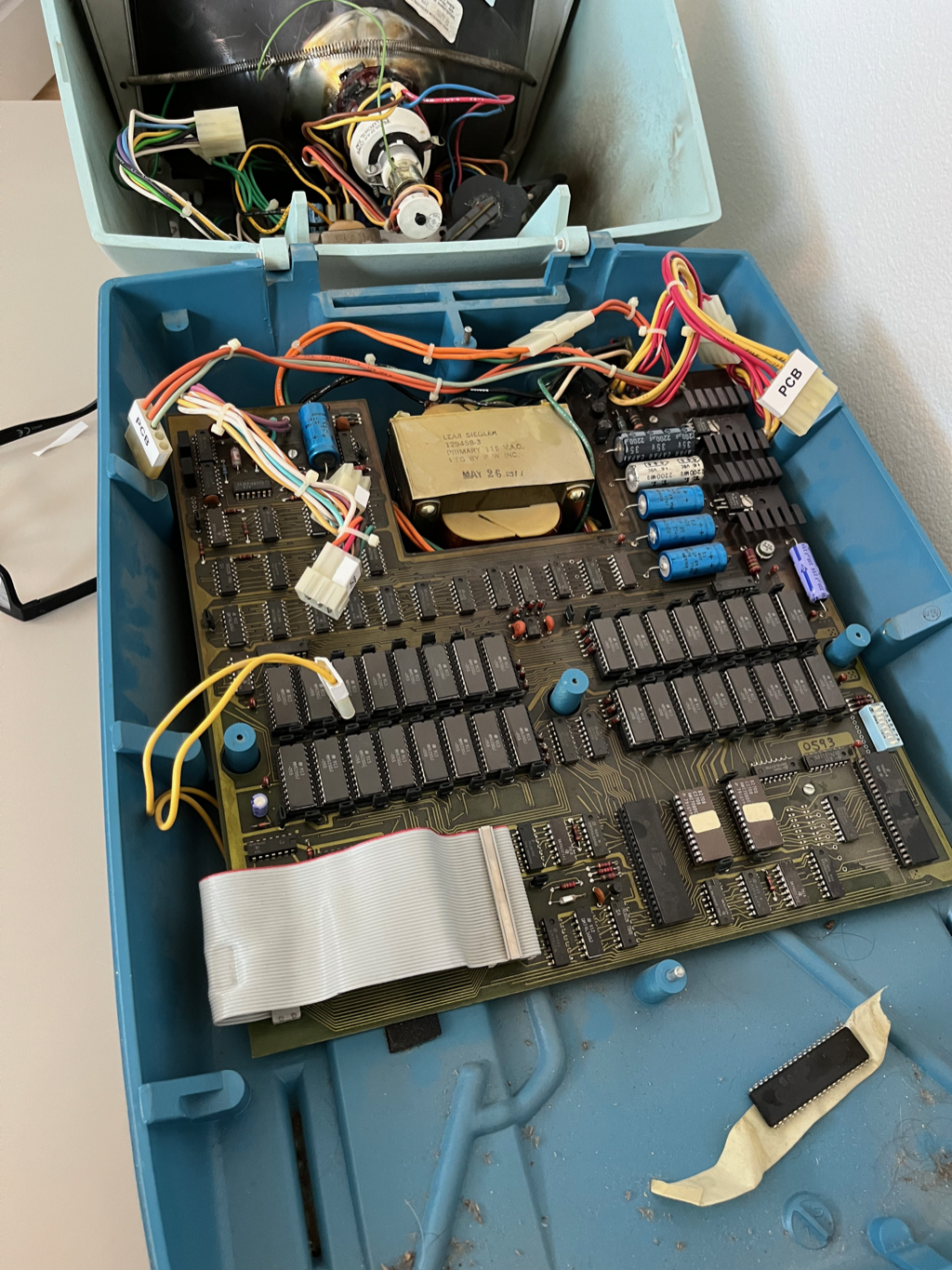
After disassembly this is what we’re dealing with. Some deep cleaning and lots of big capacitors to check, at the very least.
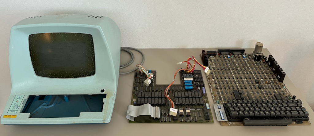
Initial Bring-Up
I decided to leave the RG512 out of the equation for the initial bring-up, to simplify things. Luckily that was just a matter of plugging the UART back in and rearranging some cables. After replacing the gummed-up power switch and testing the big caps (all fine, surprisingly) I powered it up and saw a cursor, but keystrokes weren’t showing up in half-duplex mode as expected. I instrumented the baud clock and found that it was all jittery.
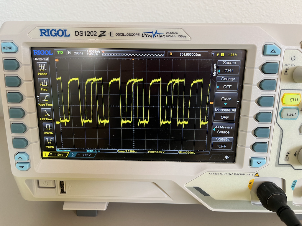
After testing a bunch of ICs I realized that the baud clock would change whenever I touched the DIP switchs! This was my introduction to “always swap out the dip switches when you’re restoring things.” After swapping the corroded blue switches for new red ones, everthing started working.
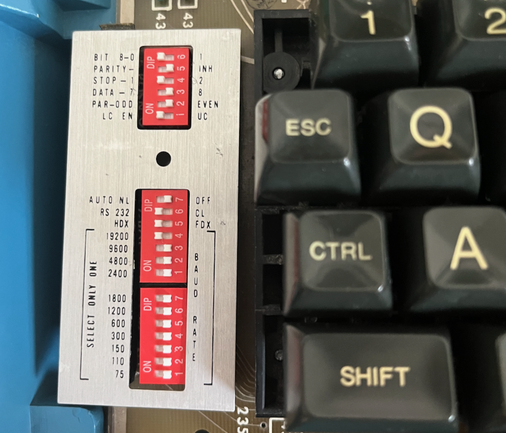
With the text terminal working I turned my attention to the RG512.
Fixing the RG512
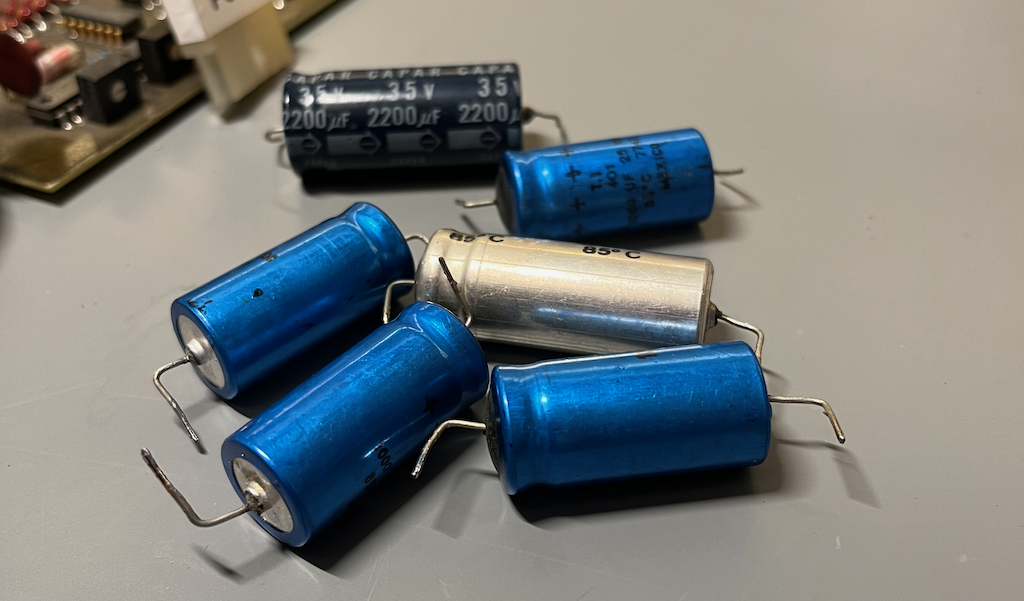
Unlike the ADM-3A board, every single electrolytic capacitor on the RG512 had gone bad, so I had to replace these before moving forward.
In order to test the RG512 I would need to send it graphics commands and wanted to hook it up as a terminal to my Mac. It took a while to figure out how to make getty run and deal with the unusual terminal type (this is pre-ANSI) but I managed to get it working, sadly without taking notes so I’m going to have to figure it out all over again some day. I was unhappy with running a serial cable across my office so I wired up an HC-05 bluetooth modem with a MAX232 transceiver and clipped it straight to back of the the DB-25 connector. This allowed me to interact with the Mac wirelessly.
The RG512 supports the Tektronix 4010 graphics language, allowing this inexpensive terminal to kind-of work with Plot 10 and other programs designed for Tektronix vector terminals. Vectors in 1024x780 are automatically scaled down to the native 512x250 raster resolution.
Sending some basic commands to draw a triangle resulted in a triangle, but an extremely wobbly one.
Note that the ADM-3A text doesn’t wobble. It’s only the graphics “layer”, which is a separate video signal that’s mixed in before it goes to the CRT.
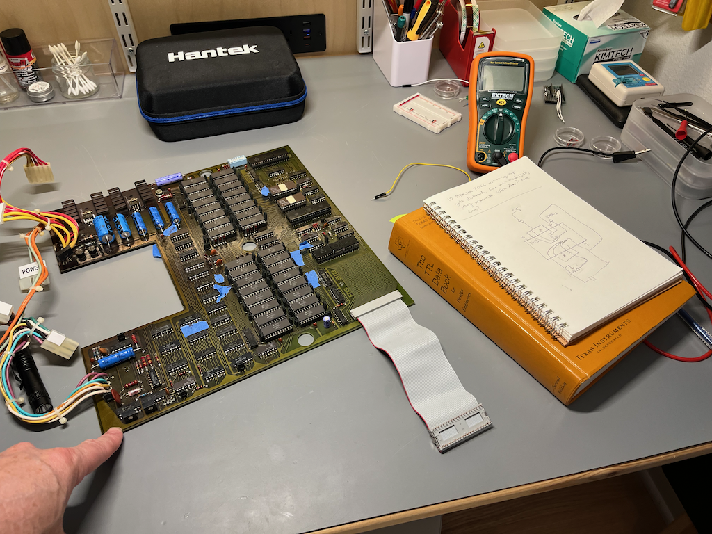
So to get to the bottom of this I rearranged the boards to put the RG512 on top, allowing me to probe it while it was running. And oddly the rippling effect went away, only to come back several minutes later. Adding a fan delayed the regression for half an hour or so, veryfiying that the problem was thermal. After a lot of probing around the video circuit I narrowed the failure down to a 7413, which the holy TTL Data Book identifies as dual 4-input positive NAND Schmitt triggers.
I did not have an extra 7413, nor could I find one as they seem to have become unobtanium, but after looking more closely I realized that the way it was being used here I could hack up something equivalent using a 74LS132.
I am not proud of this, but it did work and I was now able to draw things!
The next annoyance was getting past the default mode of all-uppercase.
Lowercase ROM
The ADM-3A has a socket for a lowercase character generator but it wasn’t populated in mine. The original part is no longer available, but with a suitable adapter a 2716 EPROM can be used instead. I designed a little adapter board and burnt the EPROM and it worked fine, the only issue being that the TL866 can’t provide the required +25V on the programming pin. Luckily it works if you bend that pin up and feed it yourself.
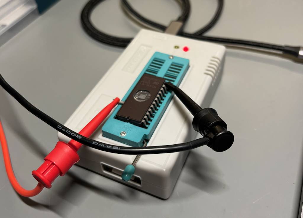
This was an easy upgrade and it really improved the feel of the terminal.
And now with the terminal electrically sound, it was time to face the final boss.
Fixing the Cataracts
CPU cataracts form in the adhesive gel between the CRT and the front safety glass. It may be chemical or bacterial, I don’t know, but once it starts it keeps getting worse and the screen eventually becomes unusable. My ADM-3A was pretty much at this point. I was initially very reluctant to mess with the CRT because it’s a gigantic capacitor that you have to discharge before it kills you, but after a year of consideration I convinced myself that I could do it safely, and did so without incident.
Following the lead of Usagi Electric I waited for a very hot day and set the screen out in the nourishing Texas sun to heat up. I started in the early morning to avoid heating the tube too quickly.
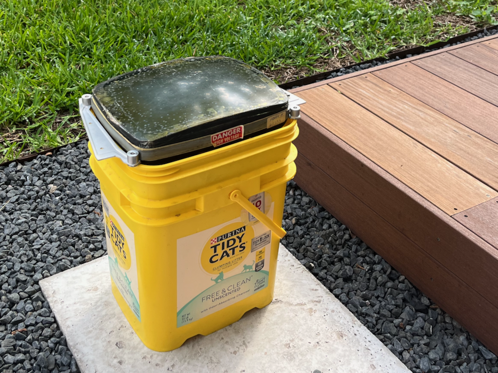
By 9am it was quite hot, and by lunchtime the gel was starting to let go. I used a plastic spudger to dig out hunks of adhesive around the edge until I was able to slowly and very gently pry the safety glass up. The name of the game here is patience, and the miracle of solar energy.
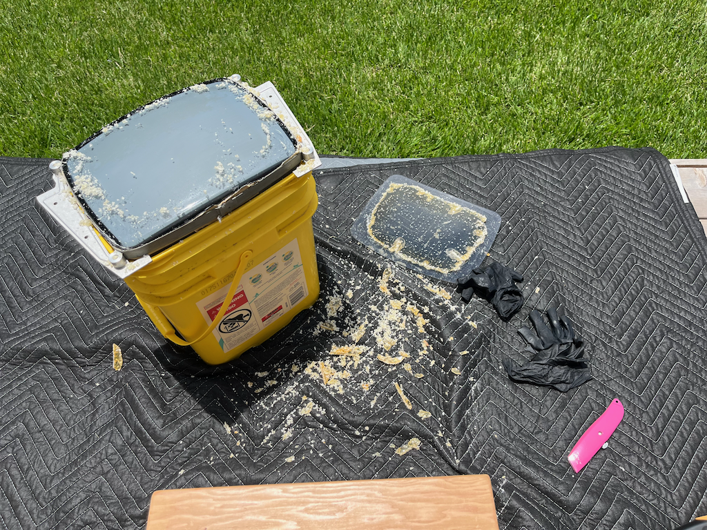
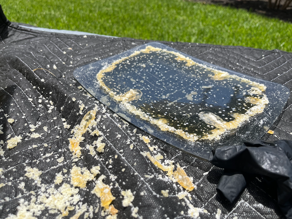
The remaining adhesive came off easily with a plastic scraper and some isopropyl alcohol. It’s very important to only use plastic tools for this because everything can scratch easily, which looks bad and can weaken the CRT. I reattached the safety glass with foam tape that was a little bit thicker than the gel layer, to allow for a little compression, then wrapped the gap with kapton tape to keep insects out.
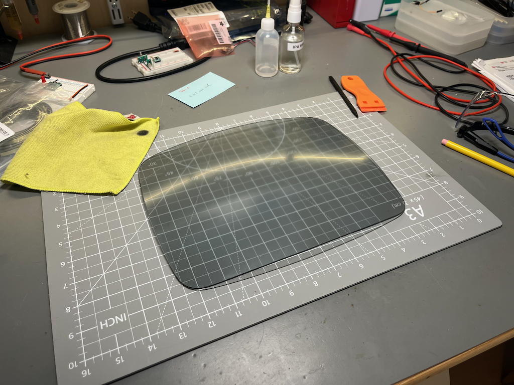
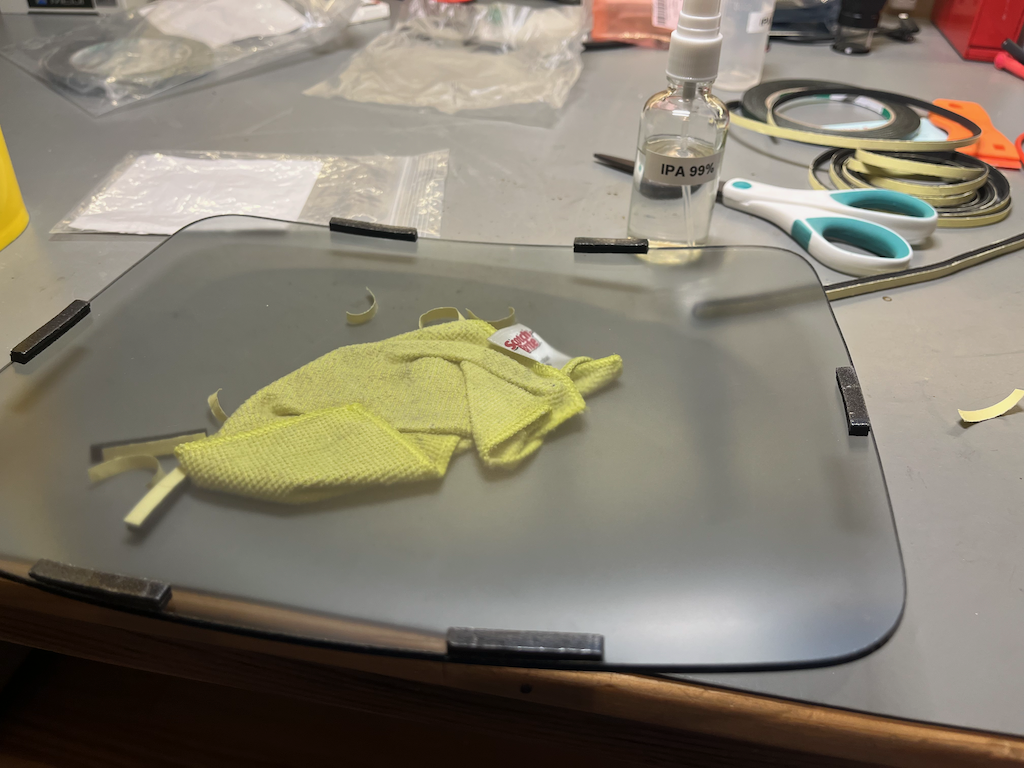
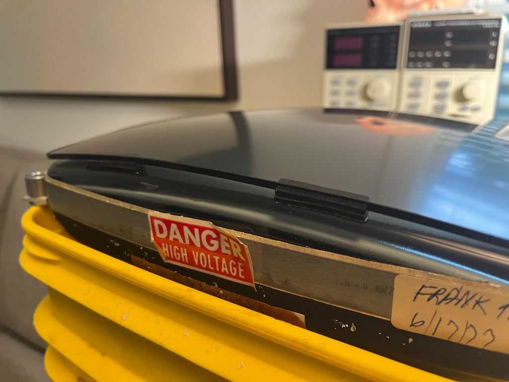
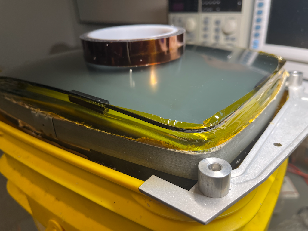
After reassembly the screen was crystal clear. A very sasisfying repair.