Testing GALs with Minipro
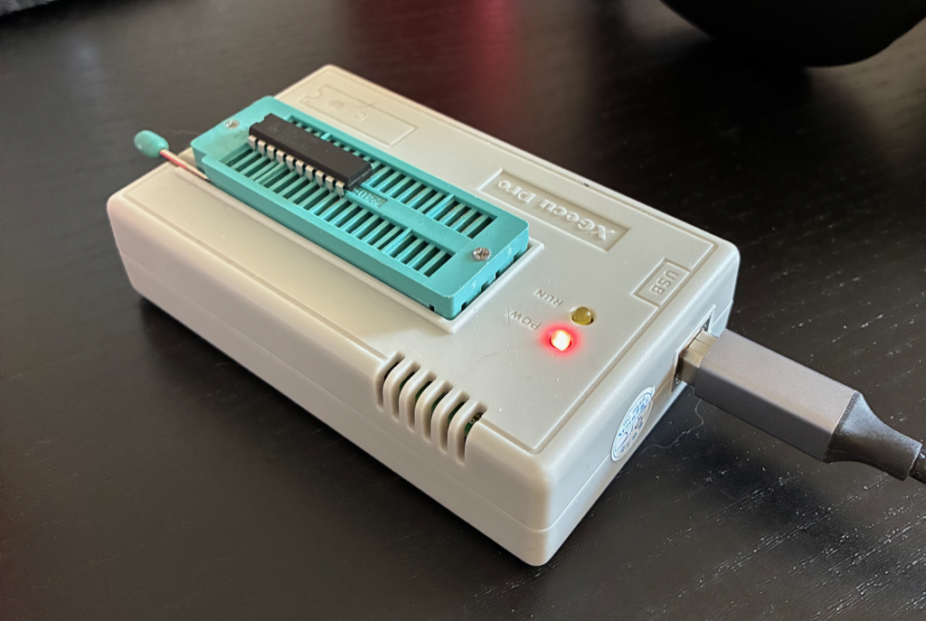
I have used GALs a lot and always ended up testing them on breadboards with jumper wires, which doesn’t inspire a lot of confidence. But I recently discovered that I can write comprehensive test suites and run them with minipro. Here’s how it works.
Testing Common Logic ICs
Minipro has a test feature for common logic chips, which you invoke with -T. For example, if I put a 74LS14 hex inverter into my programmer I can test it by specifying part 7414.
$ minipro -p 7414 -T
Found TL866II+ 04.2.123 (0x27b)
Device code: 02106811
Serial code: N95SXK8LUBRHLHXHQG4Y
USB speed: 12Mbps (USB 1.1)
      1  2  3  4  5  6  7  8  9  10 11 12 13 14
0000: 0  H  0  H  0  H  G  H  0  H  0  H  0  V
0001: 1  L  1  L  1  L  G  L  1  L  1  L  1  V
Logic test successful.
$
This test has two cases, each of which is specified as a single line of tokens, one per pin:
0and1specify input lines that will be driven low or high.VandGspecify the VCC and ground pins.HandLspecify expected outputs that will be checked.
Test cases are run in order from top to bottom (several times around to catch flaky tests).
This test and many others are defined in the logicic.xml file that minipro installs. On my machine it’s located in /opt/homebrew/share/minipro/. Here’s the specification for 7414 and a bunch of other inverters with the same pinout. Note that the <vector> elements exactly match the test output above.
<ic name="40106,7416,7414,7406,7405,7404,4584,4069" type="5" voltage="5V" pins="14">
  <vector id="00"> 0 H 0 H 0 H G H 0 H 0 H 0 V </vector>
  <vector id="01"> 1 L 1 L 1 L G L 1 L 1 L 1 V </vector>
</ic>
So the game here is to write our own test definitions.
Testing GALs
Here is a GALasm definition for a GAL16V8 that maintains five flip-flops that are set and reset by various input signals.
GAL16V8
GPIODEC

Clock  NC   ST3 ST2 ST1 RODT SODT RRST SRST GND
/OE    /ODT /T3 /T2 /T1 /RST NC   NC   NC   VCC

RST.R = SRST
      + RST * /RRST

ODT.R = /SRST * /RST * SODT
      + /SRST * /RST * ODT * /RODT

T1.R = /SRST * /RST * ST1
     + /SRST * /RST * T1

T2.R = /SRST * /RST * ST2
     + /SRST * /RST * T2

T3.R = /SRST * /RST * ST3
     + /SRST * /RST * T3

DESCRIPTION
This decodes the GPIO signals we care about.
And here is a custom test database with a specification for our GAL. We place this test in a new file of our choosing (we don’t need to modify the shared file).
<?xml version="1.0" encoding="utf-8"?>
<logicic>
  <database type="LOGIC">
    <custom name="tpolecat industries">
      <ic name="gp1" type="5" voltage="5V" pins="20">

          <!-- Clock  NC   ST3 ST2 ST1 RODT SODT RRST SRST GND
               /OE    /ODT /T3 /T2 /T1 /RST NC   NC   NC   VCC -->

          <!-- This PLD is stateful and the initial state is unknown, so enter reset. -->
          <vector> C X 0 0 0 0 0 0 1 G 0 H H H H L X X X V </vector>

          <!-- None of the other inputs should work while in reset-->
          <vector> C X 0 0 0 0 1 0 0 G 0 H H H H L X X X V </vector>
          <vector> C X 0 0 1 0 0 0 0 G 0 H H H H L X X X V </vector>
          <vector> C X 0 1 0 0 0 0 0 G 0 H H H H L X X X V </vector>
          <vector> C X 1 0 0 0 0 0 0 G 0 H H H H L X X X V </vector>

          <!-- Exit reset -->
          <vector> C X 0 0 0 0 0 1 0 G 0 H H H H H X X X V </vector>

          <!-- Tests on, one by one. -->
          <vector> C X 0 0 1 0 0 0 0 G 0 H H H L H X X X V </vector>
          <vector> C X 0 1 0 0 0 0 0 G 0 H H L L H X X X V </vector>
          <vector> C X 1 0 0 0 0 0 0 G 0 H L L L H X X X V </vector>

          <!-- ODT on and then off, test bits should remain. -->
          <vector> C X 0 0 0 0 1 0 0 G 0 L L L L H X X X V </vector>
          <vector> C X 0 0 0 1 0 0 0 G 0 H L L L H X X X V </vector>

          <!-- ODT back on, just to ensure it clears below. -->
          <vector> C X 0 0 0 0 1 0 0 G 0 L L L L H X X X V </vector>

          <!-- Reset should clear everything -->
          <vector> C X 0 0 0 0 0 0 1 G 0 H H H H L X X X V </vector>
          <vector> C X 0 0 0 0 0 1 0 G 0 H H H H H X X X V </vector>

          <!-- We don't us Z output, but check anyway -->
          <vector> 0 X 0 0 0 0 0 0 0 G 1 Z Z Z Z Z Z Z Z V </vector>

        </ic>
    </custom>
  </database>
</logicic>
Note the following:
- We specify
name="gp1"andtype="5"on the<ic>element. The name is arbitrary but it needs to be unique among the<ic>elements in the file. The type is required and is always5. - All the
<vector>elements in the shared database have anidelement, but it’s ignored so I leave it out. - The test vectors use some tokens not discussed above:
Xmeans “don’t care, don’t read or drive this pin”. I’m using it for all the NC pins.Cmeans “do a positive-going clock pulse before checking outputs”.Zis for expected high-impedance outputs.
- Because this GAL implements sequential logic it’s important to place it in a known state as the first step in our tests, because the cases are run many times in a loop. Coming back around with a different set of flip-flops set can cause surprising behavior.
I run this test with minipro, passing my custom database with --logicic.
$ minipro -T --logicic test.xml -p gp1
Using overridden database file test.xml
Found TL866II+ 04.2.123 (0x27b)
Device code: 02106811
Serial code: N95SXK8LUBRHLHXHQG4Y
USB speed: 12Mbps (USB 1.1)
      1  2  3  4  5  6  7  8  9  10 11 12 13 14 15 16 17 18 19 20
0000: C  X  0  0  0  0  0  0  1  G  0  H  H  H  H  L  X  X  X  V
0001: C  X  0  0  0  0  1  0  0  G  0  H  H  H  H  L  X  X  X  V
0002: C  X  0  0  1  0  0  0  0  G  0  H  H  H  H  L  X  X  X  V
0003: C  X  0  1  0  0  0  0  0  G  0  H  H  H  H  L  X  X  X  V
0004: C  X  1  0  0  0  0  0  0  G  0  H  H  H  H  L  X  X  X  V
0005: C  X  0  0  0  0  0  1  0  G  0  H  H  H  H  H  X  X  X  V
0006: C  X  0  0  1  0  0  0  0  G  0  H  H  H  L  H  X  X  X  V
0007: C  X  0  1  0  0  0  0  0  G  0  H  H  L  L  H  X  X  X  V
0008: C  X  1  0  0  0  0  0  0  G  0  H  L  L  L  H  X  X  X  V
0009: C  X  0  0  0  0  1  0  0  G  0  L  L  L  L  H  X  X  X  V
0010: C  X  0  0  0  1  0  0  0  G  0  H  L  L  L  H  X  X  X  V
0011: C  X  0  0  0  0  1  0  0  G  0  L  L  L  L  H  X  X  X  V
0012: C  X  0  0  0  0  0  0  1  G  0  H  H  H  H  L  X  X  X  V
0013: C  X  0  0  0  0  0  1  0  G  0  H  H  H  H  H  X  X  X  V
0014: 0  X  0  0  0  0  0  0  0  G  1  Z  Z  Z  Z  Z  Z  Z  Z  V
Logic test successful.
$
And that’s it. Really nicely designed facility I think.
Test Vector Summary
The <vector> element contains a string of N tokens, where N is the number of pins.
- Whitespace is ignored; you can pack the tokens together or spread them out however you like.
- It’s an error if you don’t have enough tokens, but if you have too many it silently becomes confused and you will end up with weird test behavior. So double-check the token count if you can’t figure out what’s happening.
Here is a summary of the supported tokens.
| Token | Meaning |
|---|---|
V, G | Power pins, VCC and ground. |
0, 1 | Input pin, drive low or high. |
L, H, Z | Output pin, expect low, high, or high-impedance. |
C, K | Clock pulse, positive-going and negative-going. |
X | Don’t care. Don’t drive or read the pin. |